 Door: CN Rood
 Blog by Meinberg.
gPTP is the name given to the IEEE 802.1AS profile of PTP. gPTP is only sort of a PTP profile. That is because gPTP is independently specified. In other words, rather than stating that it requires, forbids, and allows certain options defined in IEEE 1588, it specifies all these features independently in the IEEE 802.1AS standard. As a result, the current specification of gPTP, IEEE 802.1AS-2020, is 421 pages long, almost as long as IEEE 1588-2019. 1AS is not an easy read. Most people who read it find that it is very difficult at first, but eventually, if you do the work, very unambiguous. That is because all protocol behavior is described using state machines. If you have read 1AS and enjoyed it, I recommend The Ethics by Benedict de Spinoza for your next fun read.
IEEE 802 and IEEE 802.1 are the people who gave us Ethernet and Wi-Fi, so they have considerable credibility. They aimed the first (2011) version of gPTP at audio/video applications, but those folks usually follow Broadcast/Media standards organizations SMPTE and the Audio Engineering Society, both of whom went a different direction. There is however a great deal of interest in gPTP in the industrial automation and vehicular technology worlds.
gPTP runs on Ethernet and can also interface with the Wi-Fi Fine Time Measurement mechanism. This mechanism was created so the Wi-Fi devices can determine the propagation delays amongst them. Use of Fine Time Measurement is better than just sending gPTP messages through Wi-Fi since one generally can�t timestamp at the Media Independent Interface (MII) as one can with PTP in Ethernet due to the fact that PHYs and MACs are integrated in single ICs. So you get better accuracy using the Wi-Fi built in timing mechanism.
gPTP runs in sdoId=1, making it the only PTP Profile so far to have a value other than 0. That logically isolates it from all other PTP traffic.
gPTP uses the Peer Delay mechanism to measure network latency, and therefore requires that all switches in the network be Transparent Clock (TC) or Boundary Clocks (BCs). Note that Peer Delay is referred to as Link Delay in 1AS.
In practice BCs are deployed much more than TCs, as the first version of gPTP only had BCs. Industrial Automation applications often use multiple PTP domains in the same physical network. Furthermore, many of the BCs have a lot of ports, so if you are doing Peer Delay messages both directions in each port multiple time for each domain, that is a lot of messages, and Peer Delay processing. A better solution is to use the Common Mean Link Delay Service (CMLDS). This is a domain agnostic Peer Delay function that measures Peer Delays and makes the results available to all domains. CMLDS runs on SdoID 20016, and in Ethernet in domain 0.
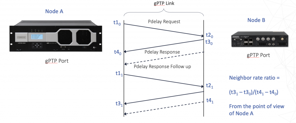
Speaking of gPTP BCs, they are only kind of BCs. They behave mostly like BCs from a protocol point of view but are the timing performance equivalent of TCs. The latter is because gPTP BCs generally don�t synchronize to the Grandmaster Clock. Instead they measure the Neighbor Rate Ratio (i.e. frequency ratio) with adjacent gPTP devices and accumulate the product of the ingress Neighbor Rate Ratios throughout the PTP communication path in the Cumulative Rate Ratio TLV attached to Announce messages (See Figure 1). The variable representation is designed to protect it from underflow and overflow errors while avoiding the use of floating-point arithmetic.

timeReveivers use the Cumulative Rate Ratio and correction fields to determine the offset of their clock from the Grandmaster Clock.
The Neighbor Rate Ratio measurements are illustrated in Figure 2.

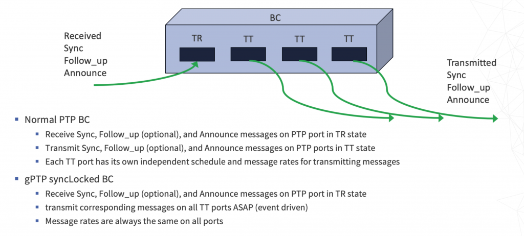
Remember that gPTP BCs behave mostly like PTP BCs.� They may act in SyncLocked mode.� This mode is described in. Figure 3.


